


Hello everyone, I am the editor. There are many types of electronic connectors, including btb connectors, but the manufacturing process is basically the same, generally divided into the following four stages:
1. Stamping
The manufacturing process of electronic connectors generally starts with stamping pins. Through a large high-speed punching machine, the electronic connector (pin) is punched from a thin metal strip. One end of the large coiled metal belt is sent to the front end of the punching machine, and the other end is passed through the hydraulic worktable of the punching machine to be wound into the reeling wheel, and the metal belt is pulled out by the reeling wheel and the finished product is rolled out.
2. Electroplating
The connector pins should be sent to the electroplating section after stamping is completed. At this stage, the electrical contact surface of the connector will be plated with various metal coatings. A class of problems similar to the stamping stage, such as twisting, chipping or deformation of the pins, will also appear when the stamped pins are fed into the electroplating equipment. Through the techniques described in this article, this type of quality defect can be easily detected.
However, for most machine vision system suppliers, many quality defects in the electroplating process still belong to the “forbidden zone” of the inspection system. Electronic connector manufacturers hope that the inspection system can detect various inconsistent defects such as small scratches and pinholes on the plating surface of the connector pins. Although these defects are easy to identify for other products (such as aluminum can bottoms or other relatively flat surfaces); however, due to the irregular and angular surface design of most electronic connectors, visual inspection systems are difficult to obtain The image needed to identify these subtle defects.
Because some types of pins need to be plated with multiple layers of metal, manufacturers also hope that the detection system can distinguish various metal coatings in order to verify whether they are in place and proportions are correct. This is a very difficult task for vision systems that use black and white cameras, because the gray levels of the images of different metal coatings are practically the same. Although the camera of the color vision system can successfully distinguish these different metal coatings, the problem of difficult illumination still exists due to the irregular angle and reflection of the coating surface.
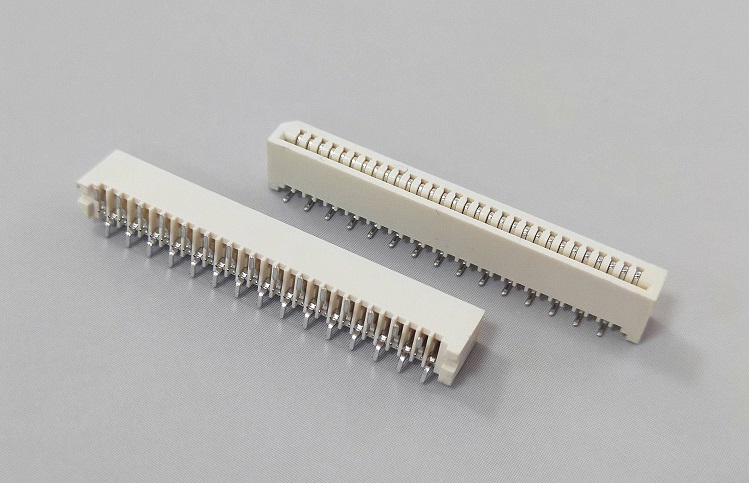
YFC10L SERIES FFC/FPC CONNECTOR PITCH:1.0MM(.039″) VERTICAL SMD TYPE NON-ZIF
3. Injection
The plastic box seat of the electronic connector is made in the injection molding stage. The usual process is to inject molten plastic into the metal fetal film, and then quickly cool it to form. When the molten plastic fails to completely fill the fetal membrane, so-called “leak?” (Short Shots) occurs, which is a typical defect that needs to be detected at the injection molding stage. Other defects include the filling or partial blockage of the socket (these The socket must be kept clean and unblocked so that it can be correctly connected to the pin during the final assembly). Because the use of backlight can easily identify the missing box seat and the blockage of the socket, it is used for machine vision for quality inspection after injection molding. The system is relatively simple and easy to implement
4. Assembly
The final stage of electronic connector manufacturing is finished product assembly. There are two ways to connect the electroplated pins to the injection box seat: individual mating or combined mating. Separate mating means inserting one pin at a time; combined mating means connecting multiple pins with the box seat at the same time. No matter which connection method is adopted, the manufacturer requires that all the pins are tested for missing and correct positioning during the assembly stage; another type of conventional inspection task is related to the measurement of the distance between the mating surfaces of the connector.
Like the stamping stage, the assembly of the connector also poses a challenge to the automatic inspection system in terms of inspection speed. Although most assembly lines have one or two pieces per second, the vision system usually needs to complete multiple different inspection items for each connector passing through the camera. Therefore, the detection speed has once again become an important system performance index.
After the assembly is completed, the external dimensions of the connector are much larger than the allowable dimensional tolerance of a single pin in the order of magnitude. This also brings another problem to the visual inspection system. For example: some connector box seats are more than one foot in size and have hundreds of pins, and the detection accuracy of each pin position must be within a few thousandths of an inch. Obviously, a one-foot-long connector cannot be detected on an image, and the visual inspection system can only detect a limited number of pin quality in a small field of view at a time. There are two ways to complete the inspection of the entire connector: using multiple cameras (increasing system cost); or continuously triggering the camera when the connector passes in front of a lens, and the vision system “stitches” the continuously captured single-frame images , To judge whether the quality of the entire connector is qualified. The latter method is the inspection method usually adopted by the PPT visual inspection system after the connector is assembled.
Post time: Sep-24-2020


